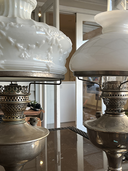
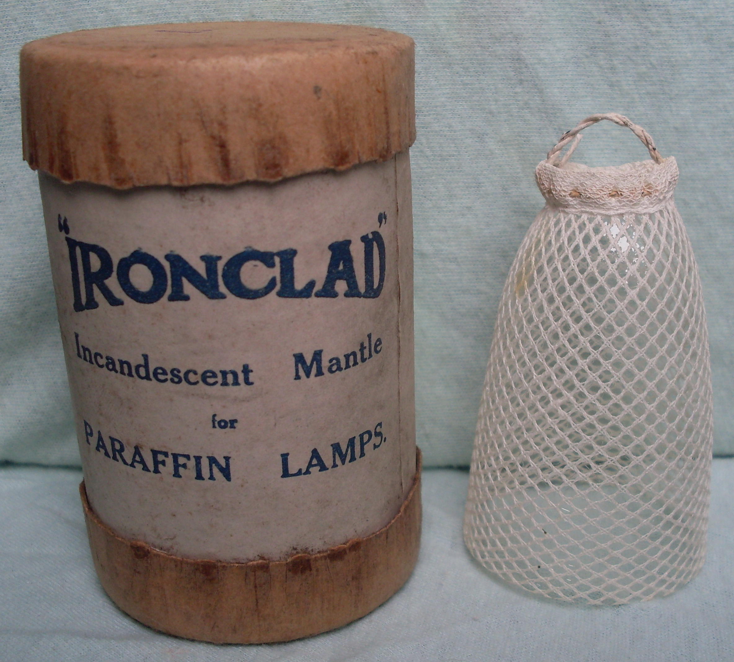
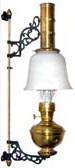
Ironclad Model 2 mantle lamp |
1920's until early in WWII |
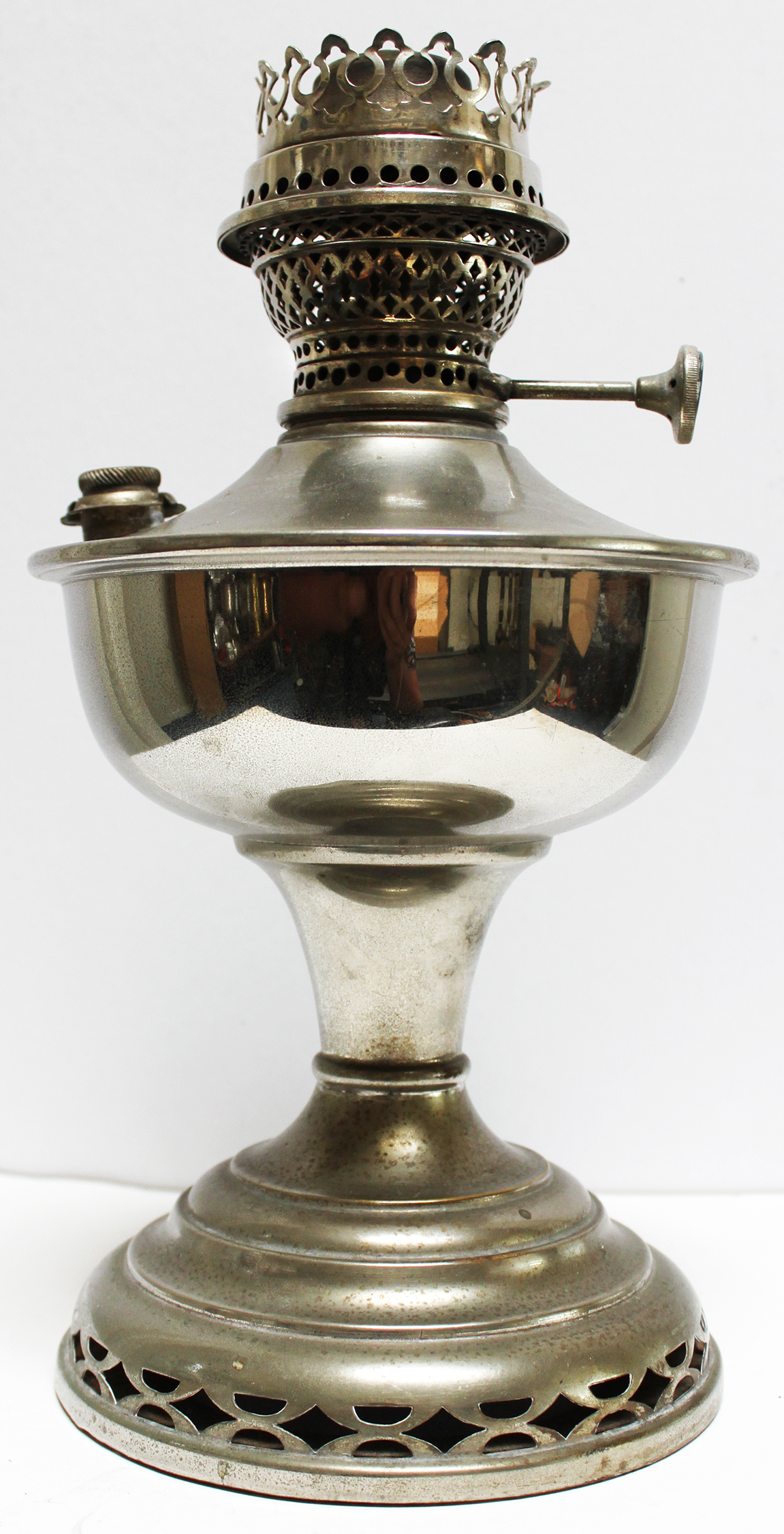 |
Very little is known about the Ironclad brand lamps. The only literature describing the lamp I have been able to locate is from Anton Kaim's book "The Evolution of the Kerosene Mantle Burner" ( Available from the author English and Dutch versions. German version is available via the German web site of Juergen Breidenstein ). Anton's description is for the 1925 model 1 version which is very similar. Neither Anton nor I have been able to locate a patent on the burner itself or to identify the manufacturer of the lamp. There is speculation that the lamp was manufactured in Germany, then the parts shipped to the UK to be assembled allowing them to claim "British Make". Anton's research shows the ironclad lamp to be virtually identical to the 1925 version of the British make, Raylite lamp introduced in 1924. I speculate that the manufacturer of these lamps independently sold lamps to Sherwood Ltd, ORAC, and Raylite and that these companies did not have a relationship with one another other than being competitors for the same market. The Ironclad lamp was marketed in the UK and Australia. The model 2 lamp in my collection was purchased from a seller in Australia.
The Ironclad brand lamps were sold and distributed by Sherwoods Limited, an English lamp factory in Birmingham, England. Sherwoods Ltd, a company that primarily produced flat wick lamps, and was managed by Sydney Harry Sherwood. Sidney Sherwood held several British lamp patents starting from around 1911, mostly for flat wick burner features. In 1924 he was granted a patent for a combined wick trimmer and filler cap. This trimmer/cap is a distinctive feature on both the Ironclad and Raylite lamps. In 1929 Mr. Sherwood, along with Blood, Ltd. received a patent for burner modifications that allowed dual use of the lamp as both a mantle lamp and as a heat source. It is my theory is that is when the Ironclad model 2 was introduced. I have no information about the ORAC brand other than they were sold by The Brant Brothers pty in Melbourne Australia. Just that they offered both a table and hanging lamp identical to the Ironclad.
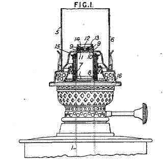
GB patent 231075 covering the combination wick trimmer and filler cap.
Page 1 (all pdf files)
Page 2
Page 3
Page 4 (drawings)
GB patent 326120 covering the use of the lamp as a heat source as well as an incandescent mantle lamp.
|
Reads British make ORAC
|
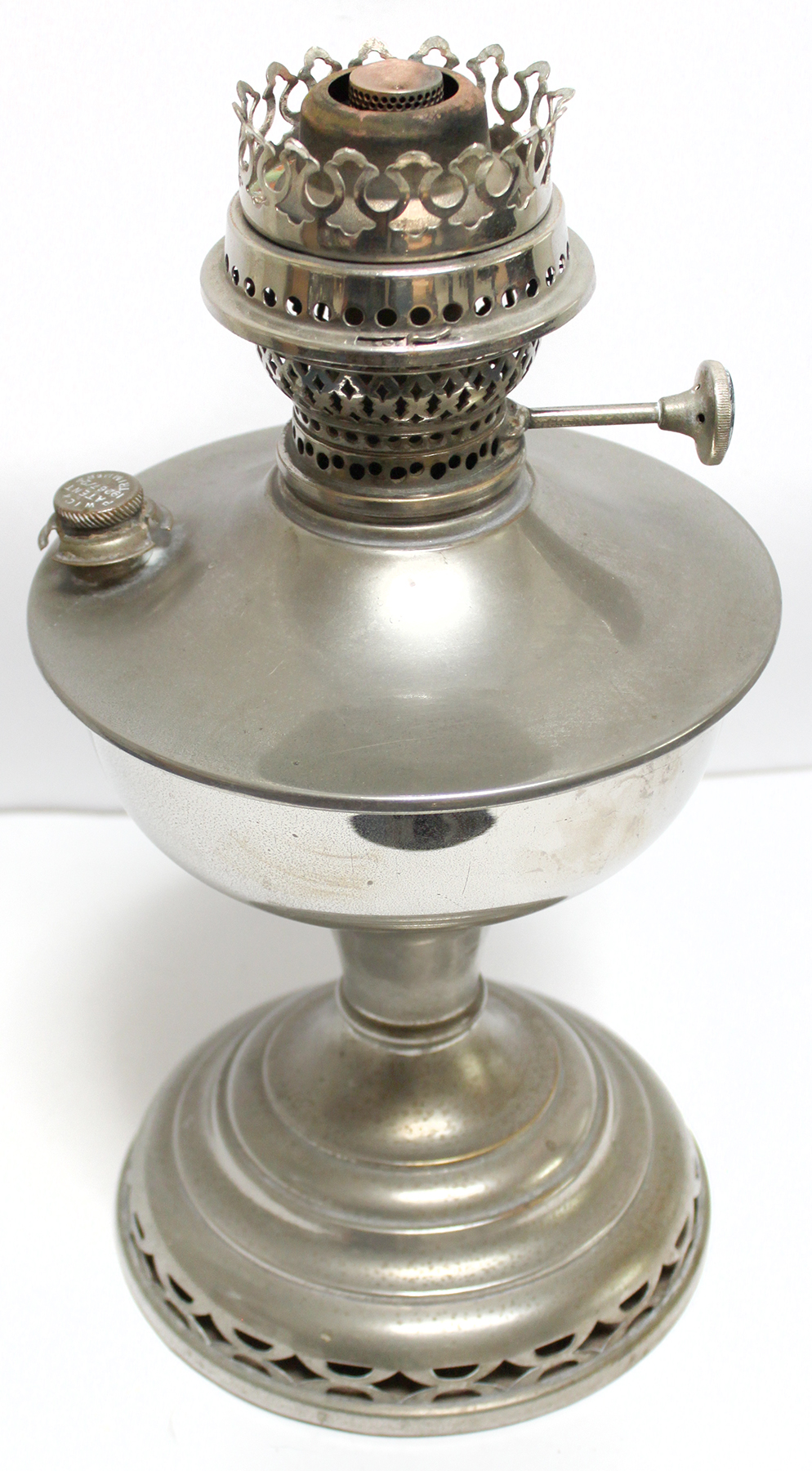 |
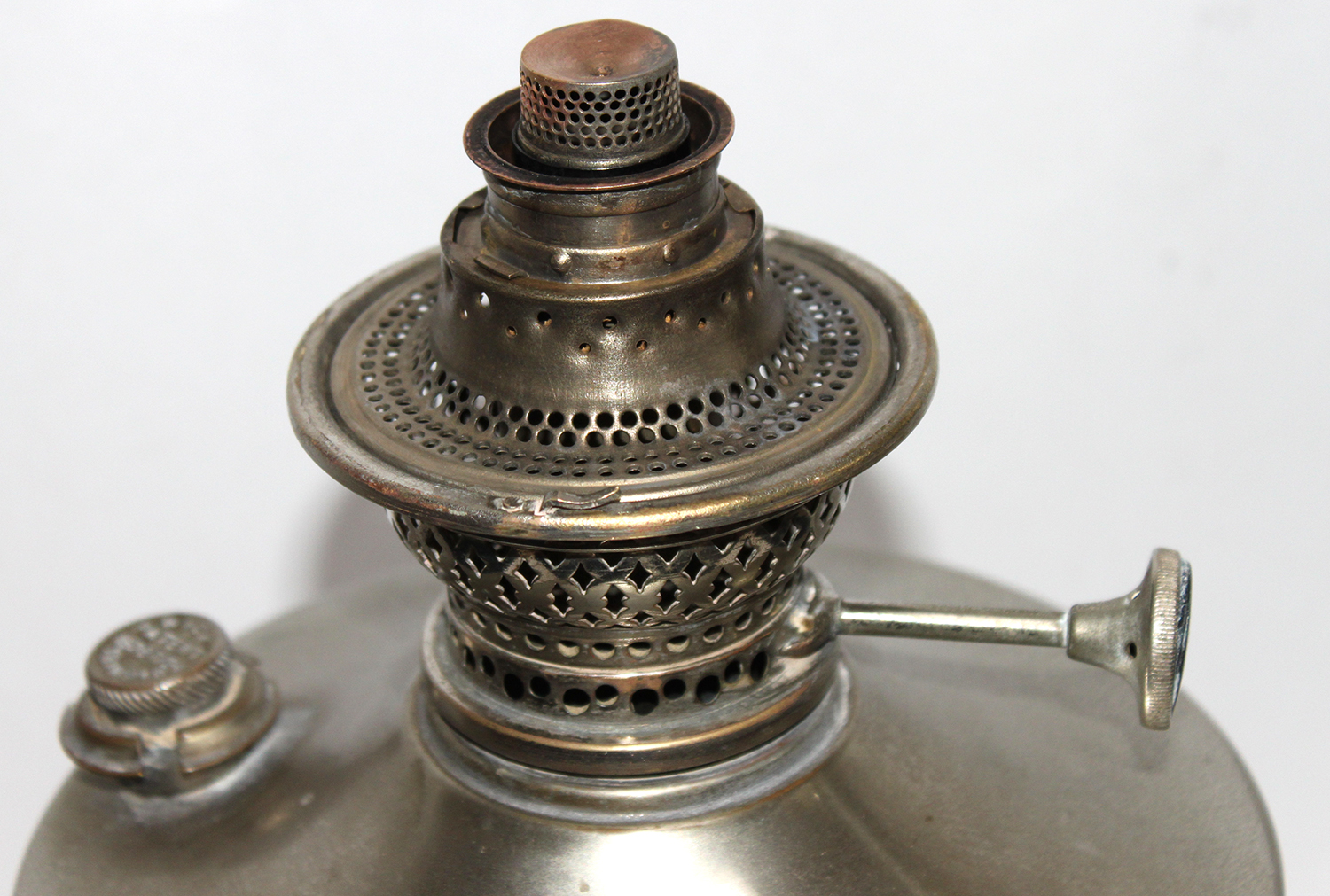
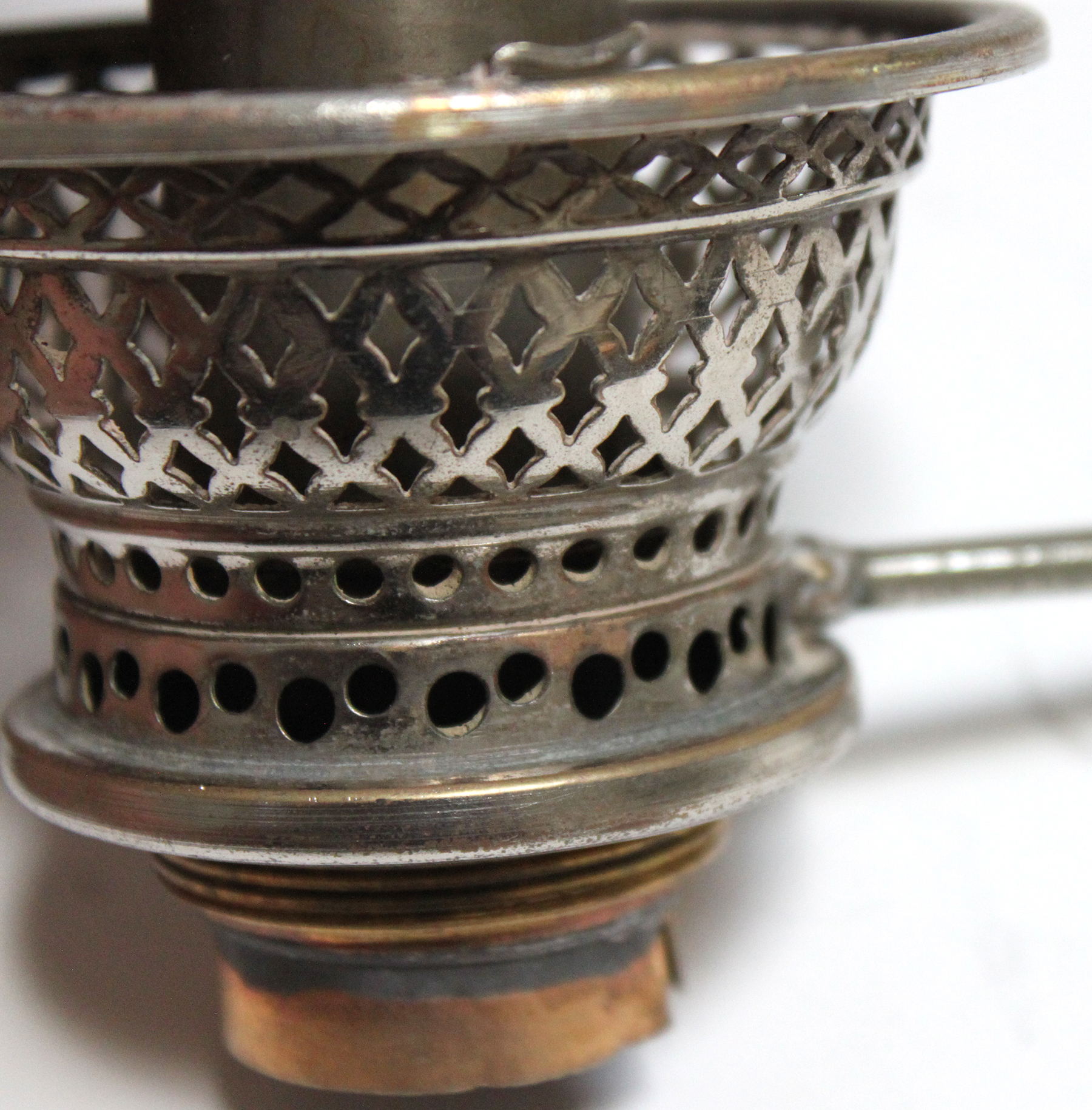
The only markings on the Ironclad mantle lamp are patent information on the wick trimmer/filler cap and on the wick adjuster knob. In this picture you can see one of the two clips that holds the gallery to the burner base. The wick adjuster shaft is housed inside the visible stationary tube. The font itself is constructed out of thicker brass sheets than is commonly associated with brass lamps, making the lamp more resistant to damage. The thicker brass may have been required to solder the oil filler threads and to support the weight of the wick trimmer/cap.
|
T.W. Sands appears to be the sole distributor of Ironclad lamps in Australia
 Fri 10 Apr 1925 Page 46.jpg)
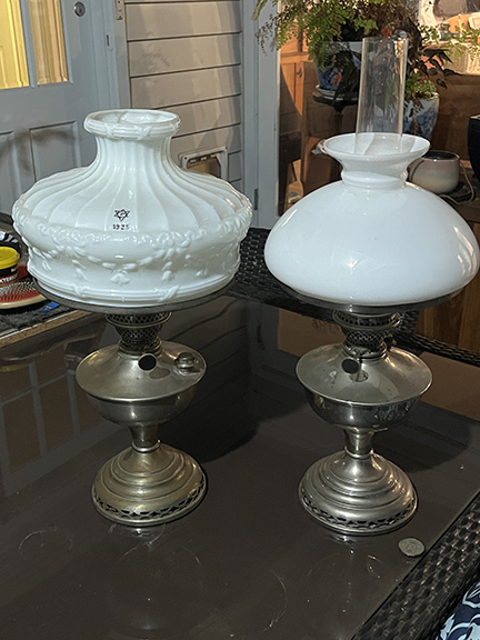
Left: ORAC lamp, right Ironclad lamp
, Saturday 6 July 1929, page 62.jpg)
1929 ad |
 Sat 20 Jul 1929 Page 61.jpg)
1929 ad |
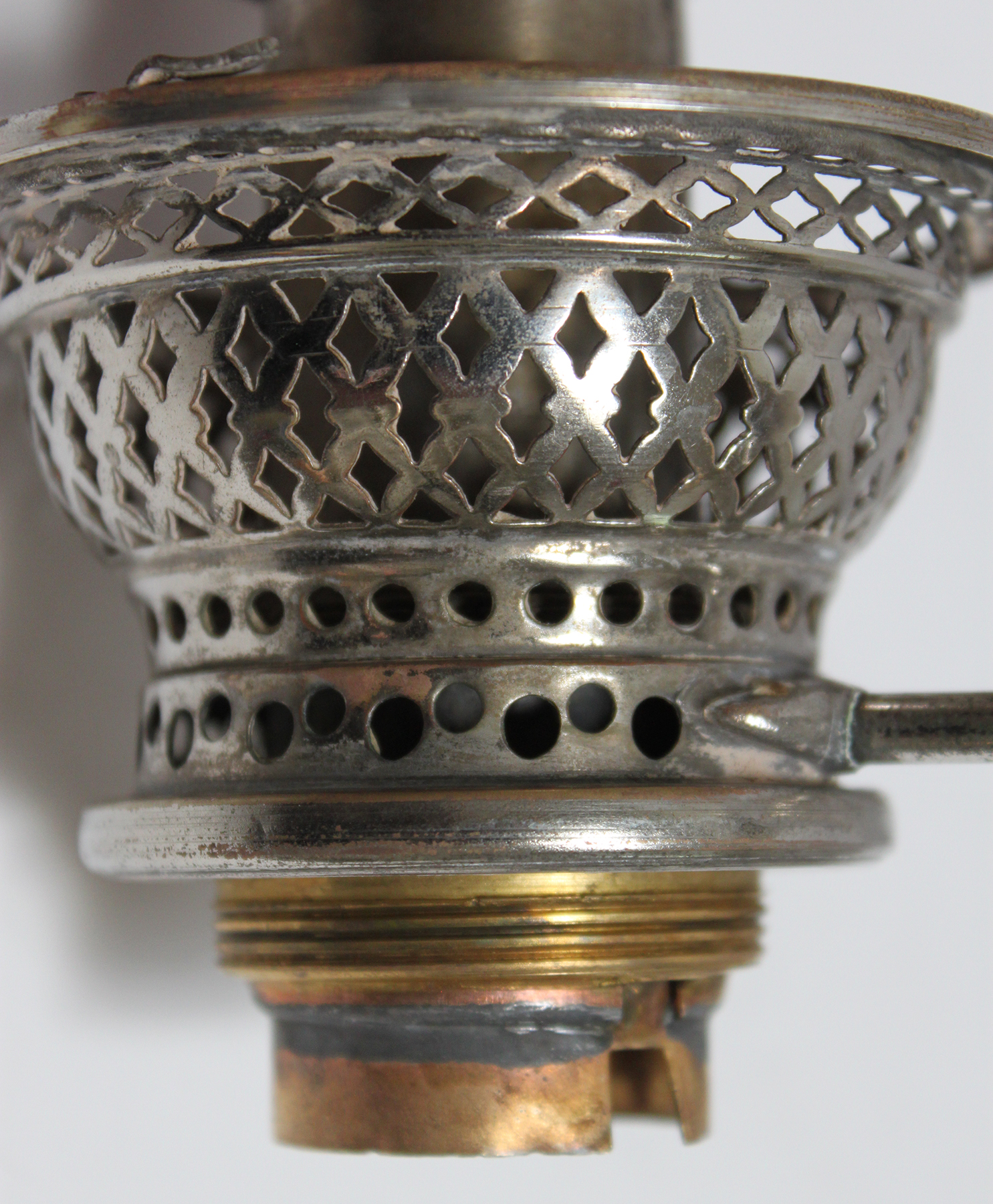
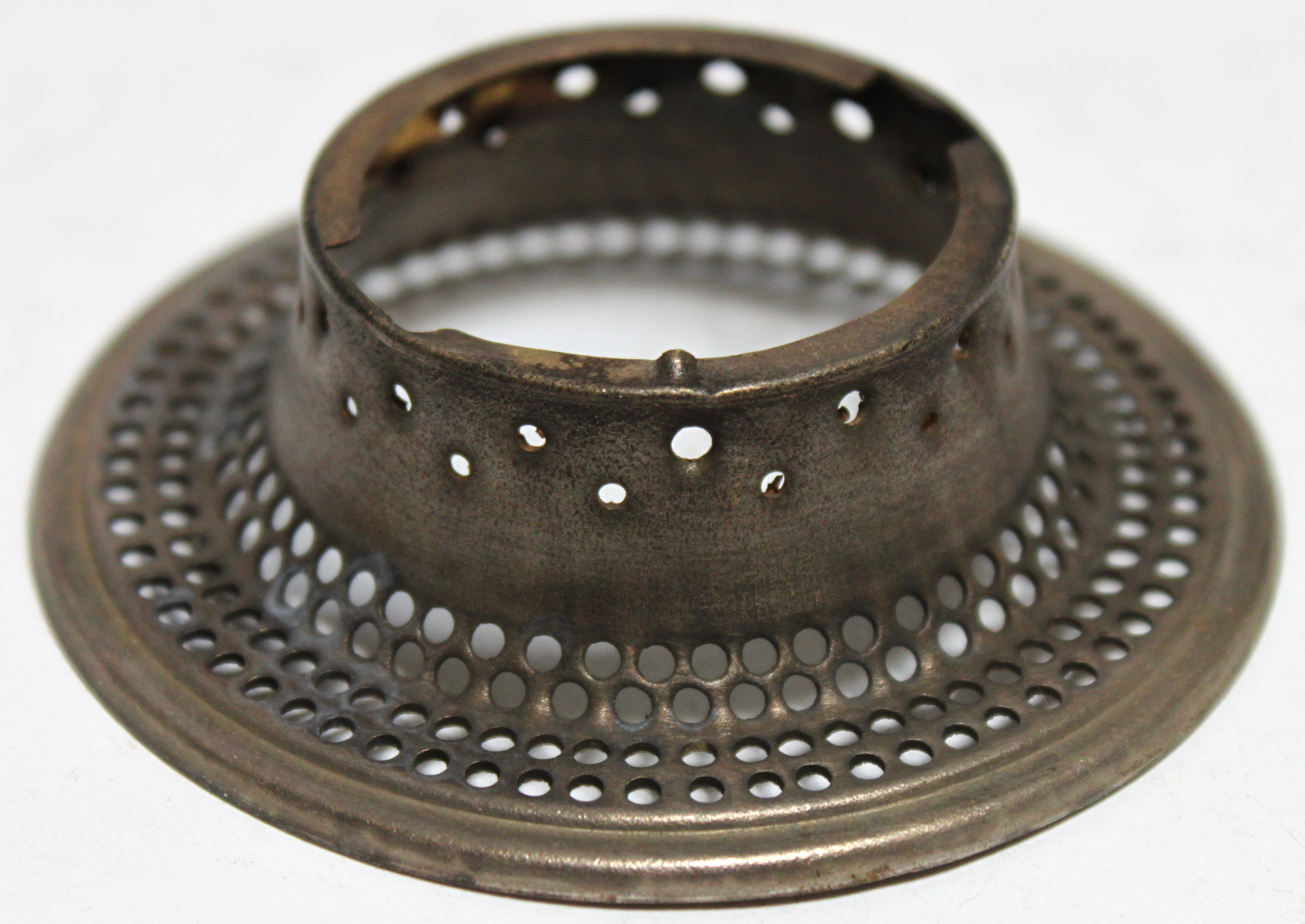
Ironclad burner with gallery removed
Removing the gallery revels a lot of information about the construction of the burner. The diameter step down of the flame spreader is located at the top edge of the centre draft tube. You can see that the top and middle flanges are attached to the outer wick tubes with punched dimples. The lower flange has tabs that lock the air distributor into place by twisting the air distributor. The top two rows of air holes on the air distributor are punched and not drilled or stamped. It is possible that the company that manufactured the parts delivered the air distributor without the top rows of holes and they were punched through at the Sherwood factory. You also can see one of the tabs that lock the gallery into place is attached to the burner basket with a small rivet. If you look closely at the right side edge of the air distributer you can see a couple of the slot holes ringing the underside of the basket top flange. These holes allow a small airflow along the outer edge of the air distributor.
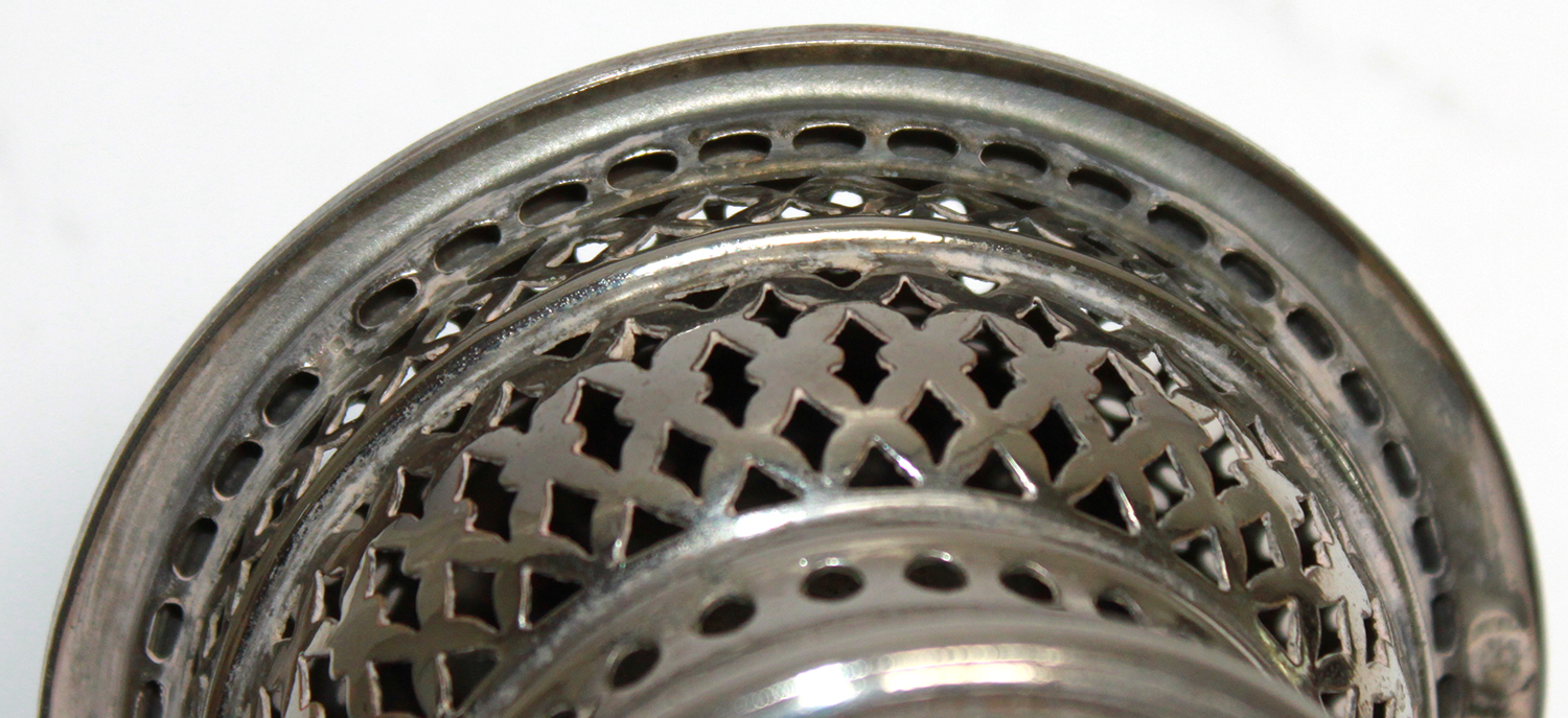
Narrow air slots on underside of burner basket top lip allows air to flow around outer lip of air distributor.
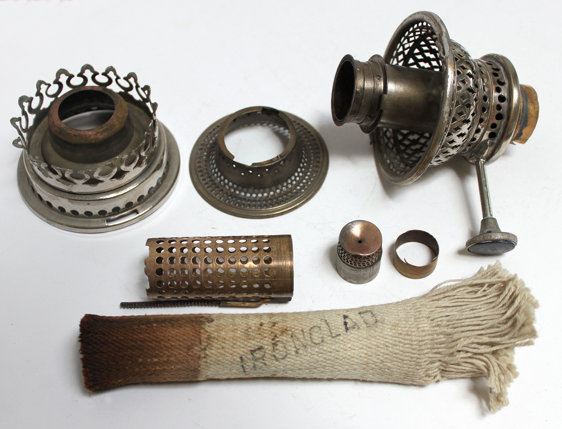
Disassembled Ironclad model 2 burner
Ironclad model 2 burner basket side view |
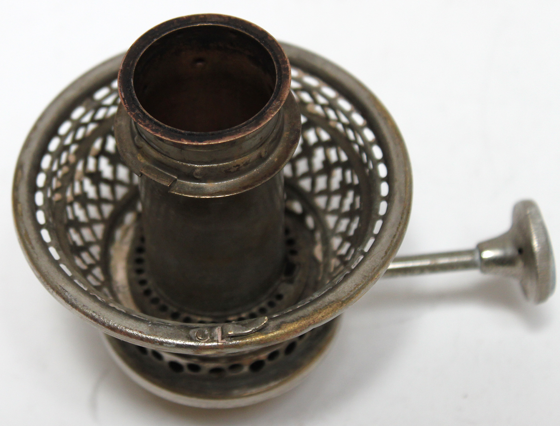
Ironclad model 2 burner basket diagonal view |
 |
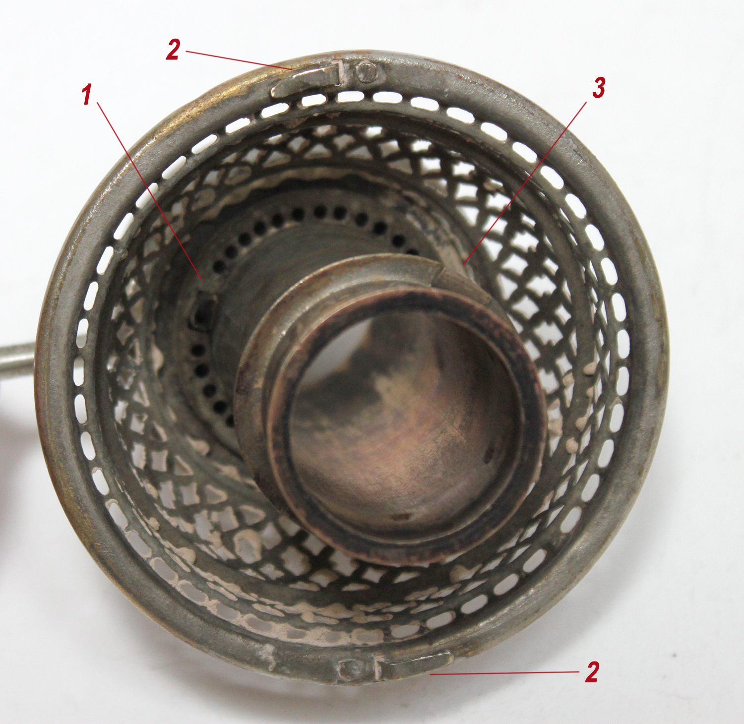
LEFT:
Side view showing the lower parts of the Ironclad Lamp, model 2 burner basket. The threads are machined brass. The outer wick tube is just a brass tube that extends below the burner basket and is soldered on at the base. Notice the slot cut into the bottom of the burner base allowing the wick holder to be adjusted higher
RIGHT:
Looking down at a bare Ironclad model 2 burner base.
1. The rectangular tube that holds the wick holder gear in place against the gear on the wick adjustment gear.
2. Tabs that hold and lock the gallery into place.
3. One of the two tabs that holds and locks the air distributor into place. |
 |
 |
Ironclad model 2 air distributor. The bottom 4 rows of holes were obviously created when the part was stamped from a sheet of brass. The top 2 rows were hand punched after the part was stamped. This reinforces the theory that the lamps were made by one company then shipped to multiple other companies for assembly and sales. The upper rows of holes might have been added to the Ironclad lamps at the Sherwood Ltd factory during assembly. |
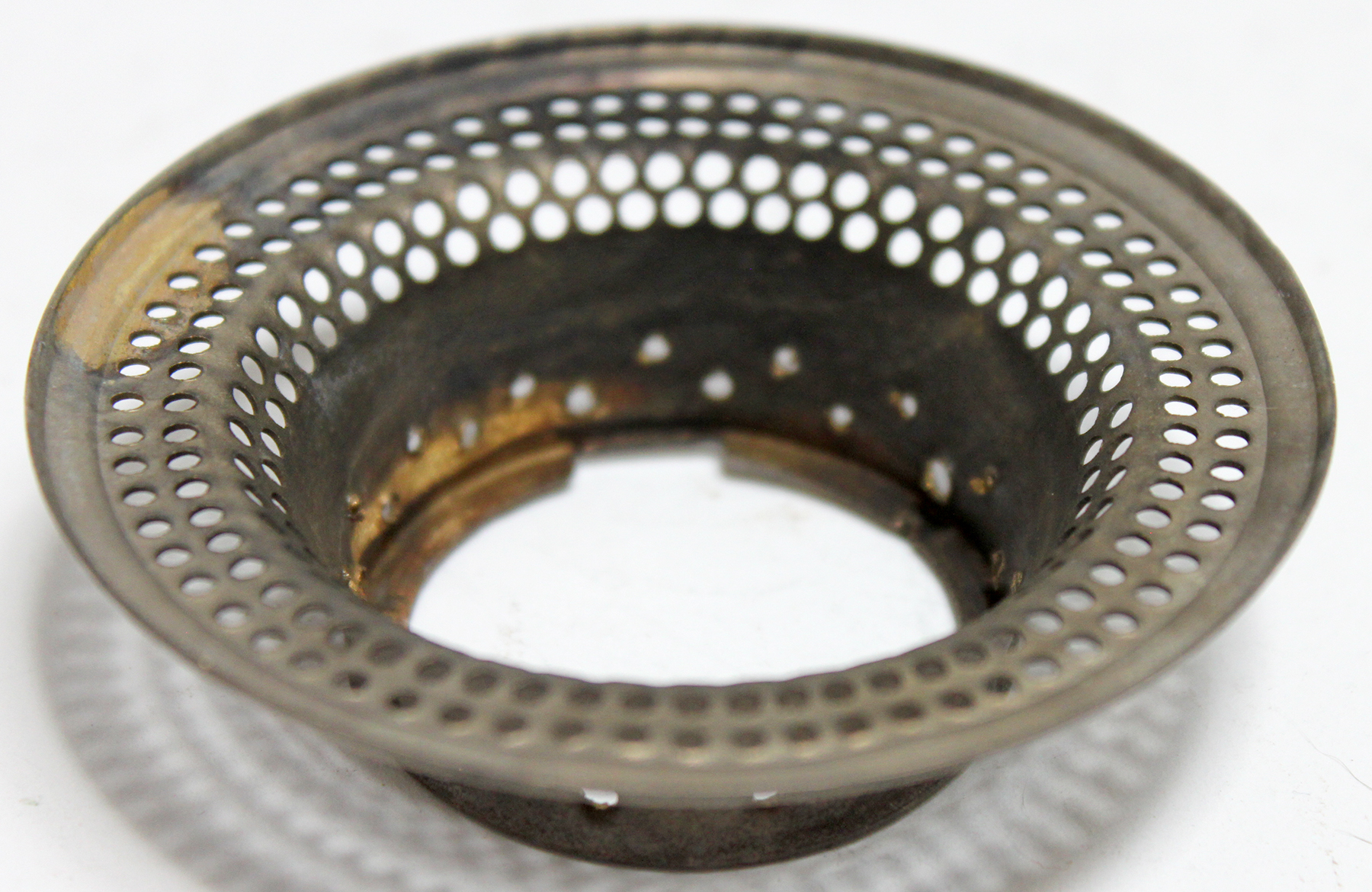 |
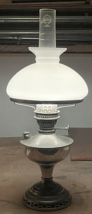
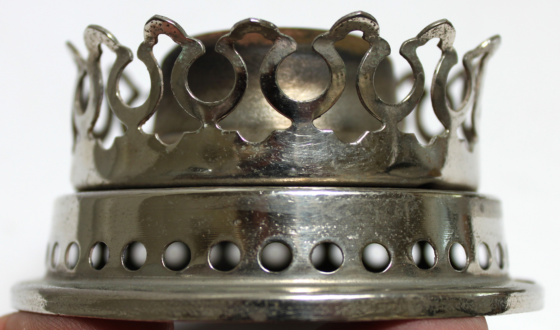
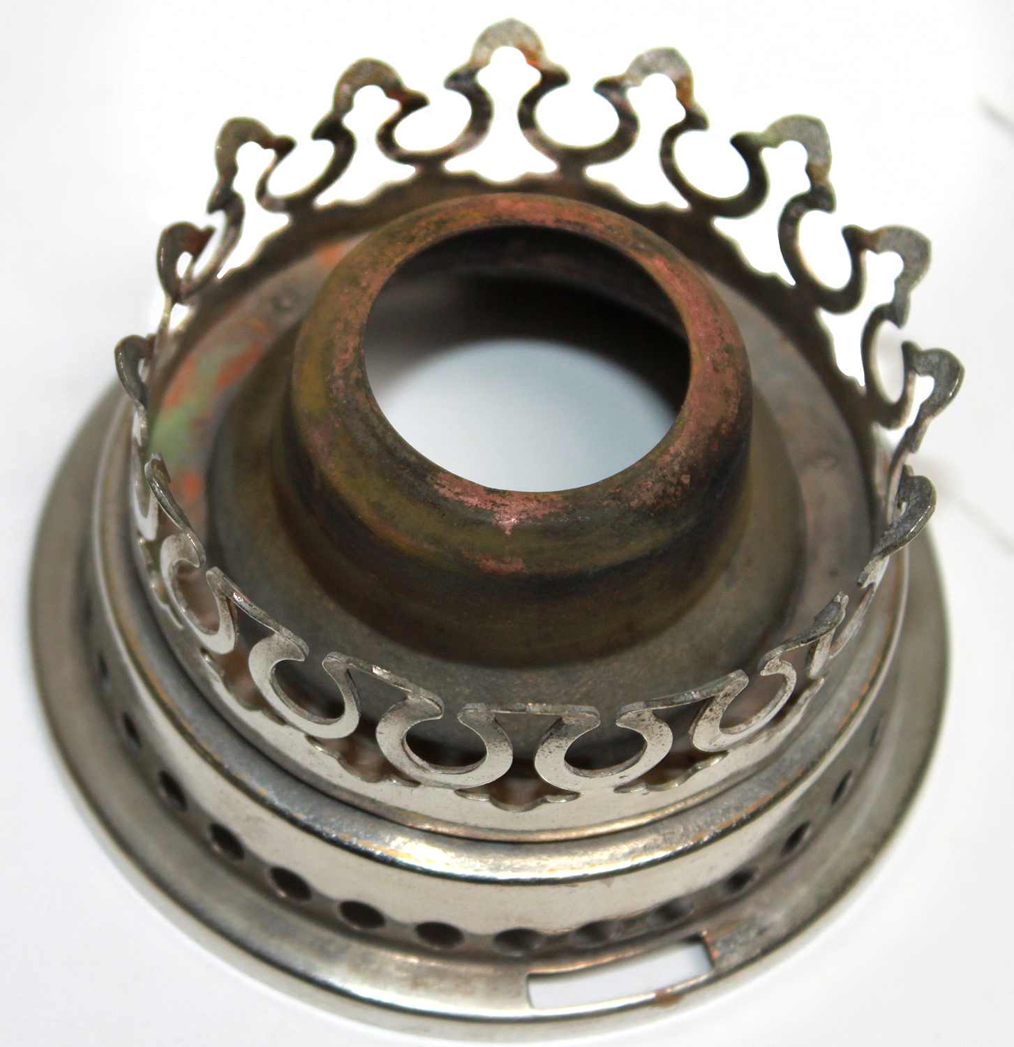
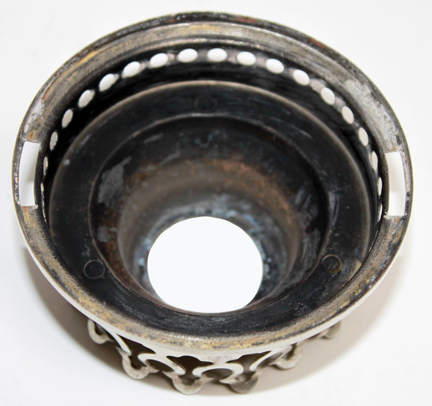
Ironclad Model 2 gallery
The Ironclad model 2 gallery was stamped in two pieces and joined together with 3 rivets. I do not have any information about the size and shape of the chimney used on this lamp. The base diameter of the chimney is 2-1/2 inches. I have not seen a mantle holder for this lamp but the shape of the gallery cone suggest that the mantle holder base is basically the same shape as that on the Colman Kero-Lite 160 lamp only slightly smaller in diameter. Like the Kero-Lite 160 frame it had a hook for suspending an unmounted mantle.
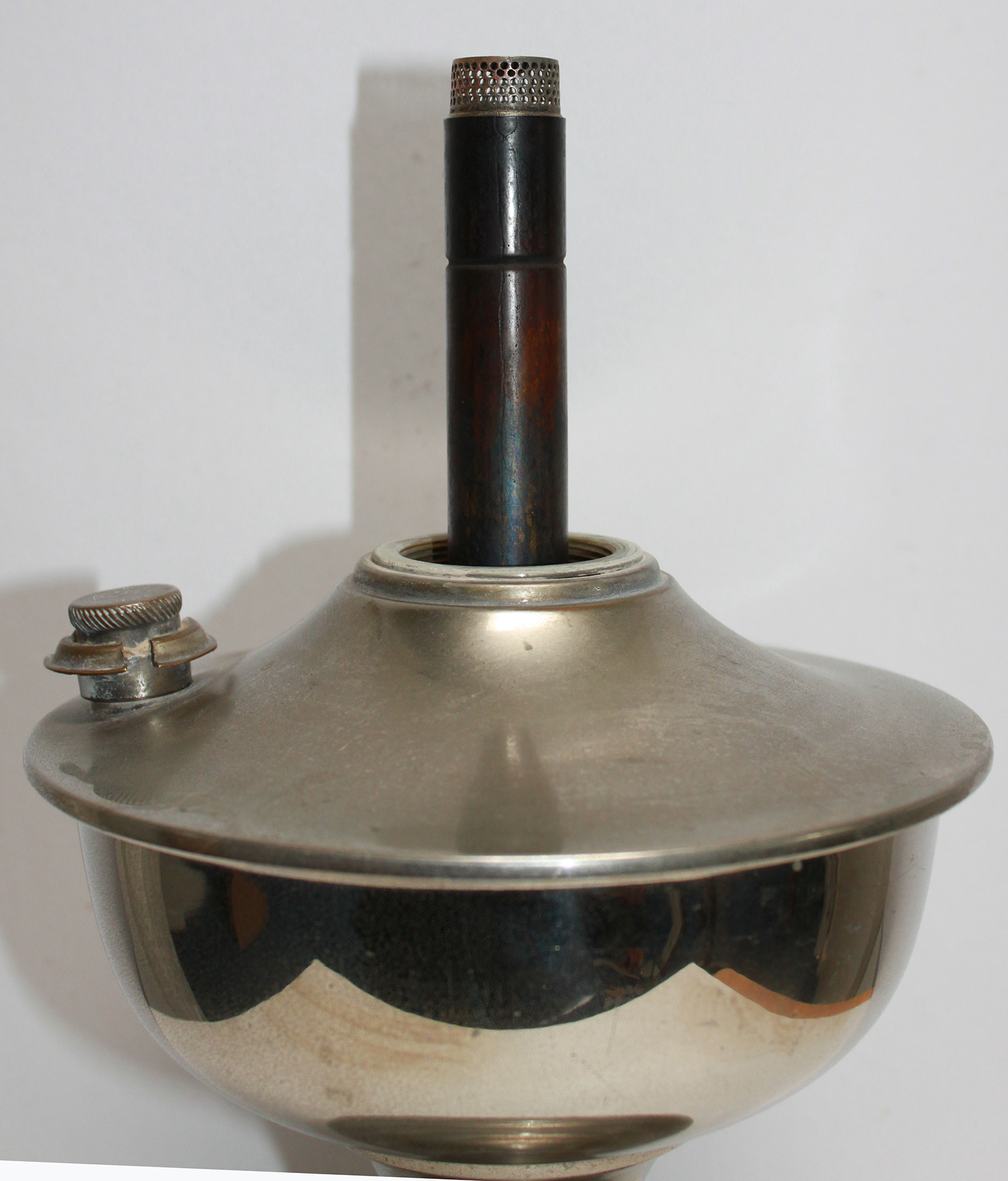 |
Ironclad model 2 inner draft tube and flame spreader
What is puzzling about this lamp is that the ridge in the inner draft tube that serves as an anchor for the flame spreader is too low for the length of the flame spreader. A short brass tube is required to raise the flame spreader to the proper height. This would make sense if the model 2 was designed to accommodate the 1929 patent covering converting the lamp to dual purpose as both a light source and heat source. Assuming the heat source conversion would require a different longer flame spreader. Another possibility would be if the manufacturer built the lamp for a longer flame spreader and Sherwood Ltd opted to use a shorter flame spreader. We will likely never know the answer. Note that the brass tube has 3 equidistant diagonal cuts into its base and the cut ends are pulled out. it is believed that this was their way of fine adjusting the location of the flame spreader in the centre draft tube so that the flame spreader step down was even with the top of the draft tube.
Also in the picture to the left you can see the threaded insert at the top of the font. The threaded insert is machined brass with machined threads. And of course a side view of the combination wick cleaner and oil fill cap. The distance between the middle of the draft tube grove and top of the tube is 1.04 inches. The flame spreader is 0.95 inches diameter at the base, 0.89 inches dia at the air holes and 1.09 inches tall. |
 |
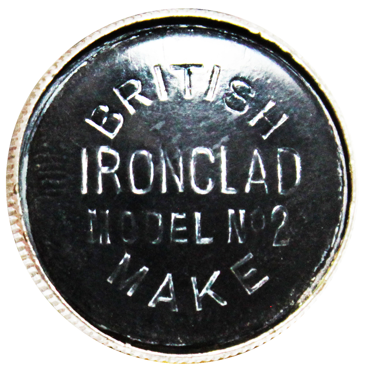
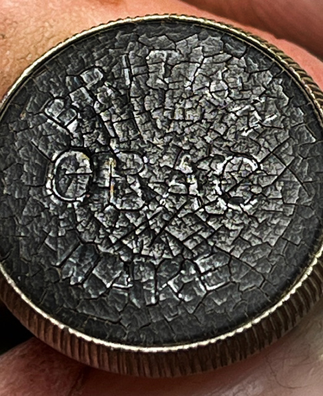
Ironclad combination wick trimmer and oil filler cap
The Ironclad combination oil filler cap and wick trimmer was patented by Sydney Sherwood in 1924 and was used on all Ironclad and Raylite lamps. Note that both the centre part of the wick trimmer/cap and the threaded base soldered to the font are both machined brass. Including the machined brass threaded insert for attaching the burner, these lamps were likely costly to manufacture.
The markings on the top of the wick trimmer/filler cap are not the patent number. 19267/24 means that Mr Sherwood was the 19267th applicant in 1924. The patent number is GB pat. No.231075. |
The Ironclad wick is an unreinforced tube stamped "IRONCLAD". The brass holder is similar to the Aladdin model 6 wick holder and can be confused at first glance. The wick holder is 1.06 inches dia, 2.68 inches long..
|
Picture courtesy of Anton Kaim
|
|
| If you would like to discuss any of the contents
please feel free to
.
© 2002, 2006 by TeriAnn
Wakeman. All rights reserved Web
site design by Marigold
Ltd.
This web site is not affiliated with Aladdin Mantle Lamp Company.
Aladdin, and Lox-on are registered trademarks of Aladdin Industries
LLC
|
 Sat 17 Aug 1929 Page 9.jpg)